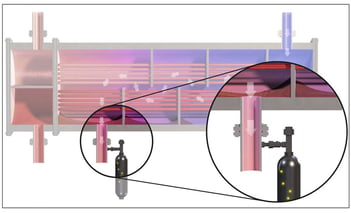
On a regular basis customers see evidence suggesting the presence of a leak; such as a drop in process efficiency or the presence of a contaminant in product. This raises the question of where in the plant the leak is occurring or is the off-spec material do to some other problem.
In this latest blog, Tracerco, part of Johnson Matthey Plc, discusses how chemical tracers allowed the customer to replace a leaking exchanger bundle and restart the unit with minimal downtime.
Tracerco has been performing online radioisotope tracer studies on feed/effluent exchangers for many years to help plants minimise lost production costs of a search for the leaking exchanger during a shutdown. Every technique has its limit and some leaks are too small to measure using radioisotope technology. Tracerco has developed a range of tracer compounds that are chemically and thermally stable and can be readily detected in samples by a specialised gas chromatograph/mass spectrometer.

To address the need to find very small leaks, Tracerco carried out an extensive research and development program looking at the application of specialist chemical tracers. The chemical tracer approach can provide plant personnel new alternatives for investigating plant operating performance with the goal of reduced diagnostic and shutdown time.
Project Field Test
In the following case study, Exchangers A and B were condensing naphtha from a crude distillation column on the shell side using raw crude as the cooling media on the tube side. Customer laboratory results showed that the naptha was out of specification with regards to color, indicating that there may be damage to the internals of the crude column or a leak in an exchanger. A Tru-Scan® was performed on the crude column and results indicated that there was no damage to the column internals, nor operational issues such as flooding or severe entrainment.
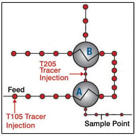
A review of the process showed that there was no sample point between exchangers on the naphtha side, so a common sample point downstream of the bank of exchangers had to be used. However, there was an injection point before each of the two exchangers on the crude side (Figure 1). The first chemical tracer, T105, was injected into the high-pressure crude inlet to the bottom exchanger (A) of the bank of exchangers. This tracer passed through the crude side of the bottom exchanger and then to the top exchanger (B). As the tracer was injected into the feed, the first sample cylinder was opened, allowed to fill, and then closed. Additional sample cylinders were opened, filled, and closed at intervals appropriate to the system.

After the last sample was collected from the first test, a different chemical tracer, T205, was injected into the crude inlet line between the exchangers. The second chemical tracer passed through the crude side of the top exchanger (B) only. The sample point was the same as for the first test.
Sample cylinders were analysed for tracer presence.
Project Analysis
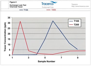
Flowrates of the crude and naphtha through the exchangers indicated that the residence time should have been about 2 minutes each. Analysis of the first chemical tracer (T105) appeared in sample A5 with the maximum concentration of tracer seen in sample A6 (Figure 2). The residence times matching these samples was 2.5 and 3 minutes. Since the residence times were not known exactly, these results indicated a leak either near the crude outlet of the bottom exchanger (A) or near the crude inlet of the top exchanger (B).

The second tracer (T205), injected into the crude feed to the top exchanger, was detected in samples B2 and B3, with the highest concentration of tracer found in sample B2. Since the analysis only found tracer in the first 2 samples, the leak appeared to happen near the crude inlet of the top exchanger (B).
The test data showed a strong positive tracer response indicating that the top exchanger (B) was indeed leaking. But was the bottom exchanger (A) also leaking? The residence time of the chemical tracer found in the naphtha samples showed that the tracer had likely already passed through the bottom exchanger (A) and was near the entrance to the top exchanger (B). Therefore the conclusion was made that only the top exchanger (B) was leaking.
Based on the process rates through these exchangers, the amount of tracer injected, and the amount of tracer in the samples, the leak size was calculated to be approximately 100 ppm (0.01%)
Customer Conclusion
These exchangers were floating head design, and experience of this exchanger type when trying to detect small leaks was found to be very difficult and time consuming. With the knowledge that the B exchanger was leaking, the plant was able to shutdown and replace the leaking bundle and restart the unit with minimal downtime. After restart, the lab analysis showed the naphtha quality problem had been eliminated.
This chemical tracer approach is only offered by Tracerco and can provide plant personnel new alternatives for investigating plant operating performance with the goal of reduced diagnostic and shutdown time along with reduced maintenance costs.
Click here to download a copy of one of Tracerco's many exchanger leak testing case studies.
If you want to learn more about how Tracerco's Exchanger leak testing technology please complete the form on our contact us page at http://www.tracerco.com/contact-us and request additional Tracerco Diagnostics™ Leak Study case studies or schedule a lunch and learn presentation.