In FCC Units (Fluidised Catalyst Cracking Units), the atmospheric residue from the distillation is cracked to LPG, naptha and other components. This sometimes leads to “invisible” deposits inside the riser.
In this latest blog, (also featured on the FCC Network), Tracerco will discuss how ThruVision™ Scans can be used to identify these “invisible” deposits at an early stage.
Case study for identifying deposits inside a FCCU's riser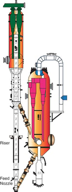
Bayernoil operates two FCCUs to convert heavy hydrocarbons. In the FCCU, the feed is injected through nozzles with lifting steam into the hot catalyst flow (about 700°C) from the regenerator, Inside the riser, the hydrocarbons are cracked into smaller compounds. At the top of the riser, catalyst and vapourised hydrocarbons are separated. The catalyst flows to the regenerator where the coke is burned and the hydrocarbons go to the main fractionator column. Some of the coke generated will remain in the riser as deposits on the inner wall. If these deposits build-up and become too thick, this can cause problems. The throughput will be reduced and the FCCU must be shut down for cleaning operations.
Caused by turbulent flow, the material hits the hot inner walls and coke builds up over time. This process is influenced by the catalyst throughput, the condition of the feed nozzles and the lifting steam rates. To detect coking in the riser at an early stage and to start actions to prevent the build-up, the Bayernoil FCCUs are regularly investigated by ThruVision™ measurements performed by Tracerco.
Most of the coke deposits are found above the feed nozzles. A ThruVision™ study is performed at a fixed elevation to generate a detailed cross-sectional density profile. Several measurements are taken at selected positions. For this study, a radiation source is placed in the first of nine positions, which are evenly spaced around the circumference of the riser. A measurement is taken with a detector positioned opposite the source. Then, the detector is moved to four more positions to the right and to four positions to the left of the first detector position, creating an arc of nine readings from the one source position. The source is then moved to the second position and nine more readings are collected. A total of 81 readings are collected (Figure 2).
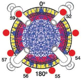
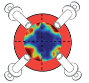
Figure 2: Cords inside the riser Figure 3: Illustration of deposits could inside the riser
The gathered data from the ThruVision™ Scan is used to generate a tomographic picture showing different densities which directly refer to the deposits inside the riser. (Figure 3). The riser of the Bayernoil Vohburg site was replaced during a turnaround in 2013. To get a better understanding of the interpretation of the ThruVision™ Scans, this riser was investigated by Tracerco to compare the picture with the real deposits. Figure 4 shows the correlation of the red and yellow areas in the ThruVision™ results with the coke deposits in the riser segment.
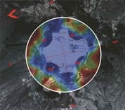
Figure 4: Overlay of a tomography and a photo from the coke deposits
The new riser was scanned to obtain baseline reference data. (Figure 5) These ThruVision™ Scans are repeated regularly to monitor the unit and to help develop the best plan for its performance and shutdowns for cleaning.
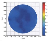
Figure 5: Baseline reference scan without deposits
Tracerco ThruVisionTM scans can be useful to determine the following:
- Study the effect of steam injection on fluidization.
- Determine the uniformity of distribution between the catalyst and feed.
- Identify flow inefficiencies, such as catalyst maldistribution.
- Determine if a nozzle is plugged or fouled.
If you want to learn more about how Tracerco technology enable you to make the right decision, click here to request more information.
Johnson Matthey offers a range of specialised FCC additives through the INTERCATTMJM brand. INTERCATJM FCC additives are used in refinery FCCUs globally to tailor the selectivity of the unit, boost LPG yield at the expense of LCO and HCO, decrease bottom yields, and reduce regenerator SOx, NOx and CO emissions. INTERCATJM addition systems allow refiners to add catalyst and additives to the FCC on a near continuous basis thus reducing additive and catalyst usage, improving FCC profitability through yield improvements, and reducing maintenance costs. The INTERCATJM addition system IMS controller, monitors and logs daily catalyst and additive additions, simplifying negotiation of final FCC emission limits through data compilation and verification of testing results. For more information, visit the website.