Tracer technology is proven to be critical to assess remaining oil saturation measurement in a reservoir following secondary recovery. It allows the measurement of remaining oil saturation between wells, rather than just surrounding a wellbore. This technique is normally used before and after an Enhanced Oil Recovery (EOR) project to establish changes in crude oil saturation.
In this blog we will discuss using a case study example, how our range of specialist chemical tracers can allow operators to identify the amount of remaining oil saturation in a mature waterflood and determine the effectiveness of specific enhanced oil recovery techniques at reducing remaining oil to residual levels.
The ChallengeAn operator working in the southern Sultanate of Oman was challenged to improve recovery from a formation in a major oil-bearing sandstone reservoir. Data from core flood tests and from reservoir simulation suggested that this goal could be achieved using an EOR technique known as alkaline surfactant polymer (ASP) flooding. The financial investment in such an EOR program is high and so there was a strong desire to ‘derisk’ the decision by proving ASP flood effectiveness within the constraints of a pilot area.
To effectively measure the benefit from an ASP flood, Tracerco was brought in as a partner in a multiyear, three part project that used tracers to establish:
(1) how waterflooding was behaving in the formation
(2) the remaining oil left behind after the waterflood and;
(3) the residual oil saturating the reservoir after an ASP flood.
Over a period spanning several years, Tracerco’s non-partitioning and partitioning water tracers were used to achieve these technical goals and establish the financial viability of the ASP chemical flood program.
The Solution
The formation is an oil-bearing play comprised of multiple glacial sediments layered upon each other. Four key lithofacies comprise the formation: a sandstone zone which serves as traditional reservoir rock, a shale zone that is the reservoir seal, and finally zones of sandy and silty diamictite. Though diamictite is traditionally considered a “waste” rock, some zones of thick silty diamictite have proven effective seals for hydrocarbon accumulation while some zones of sandy diamictite have the potential to be unconventional reservoir rock. Within the sandstone reservoir rock, one layer is the predominant oil-bearing layer with an API gravity of 22 and an average oil viscosity of 90 cP, but the play is highly heterogenous with numerous intra-formational seals.
In phase one of the tracer study, a non-partitioning water tracer was used during an inverted five-spot waterflood pilot study. After a month of continuous water injection, a slug of liquid water tracer was injected alongside water into a central injection well, I-1 (see Figure 1). After injection, samples were taken from the production wells that also comprised the inverted five spot pattern (P-1, P-2, P-3, and P-4) at regular time intervals to establish if and when the injected tracer would travel from the injector to these production wells. Further away, five production wells (P-5, P-6, P-7, P-8, and P-9) were also tested at regular time intervals for presence of the injected tracer to establish fluid streamlines within the possible injector influencing area.
In phase two, a combination of partitioning and non-partitioning water tracers measured the remaining oil
saturation within the pilot area. At the start of phase two, the pilot area was considered a mature waterflood with 2.7 pore volumes of water pushed through the reservoir.

Figure 1 - Well layout within the pilot area.
In this phase, slugs of the partitioning and non-partitioning water tracers were co-injected alongside the waterflood. The non-partitioning water tracer marked only the aqueous phase and would be displaced only by water along the streamlines the water travelled between injector and producer wells. The partitioning water tracer, however, had weak affinity to oil. As it was displaced by the waterflood, a fraction of the partitioning tracer moved from the aqueous phase into the immobile remaining oil it encountered in the
reservoir. Within the remaining oil, the velocity of the non-partitioning tracer was reduced to zero until it moved across the oil-water interface back into the mobile aqueous phase. Along its path from injector to producer, this behaviour repeated itself with the partitioning tracer moving more slowly than the non-partitioning tracer because of its residence time within the oil phase. By measuring the degree to which the partitioning tracer was impeded compared to the baseline non-partitioning water tracer, the remaining oil saturation in the reservoir was calculated. Based on the fluid streamlines the tracers followed, the waterflood sweep efficiency and ultimate oil recovery were also established.
In phase three, the waterflood was replaced with an alkaline surfactant polymer (ASP) flood. This chemical EOR flood was predicted to displace and recover some of the remaining oil that could not be mobilised by a waterflood. After injection of the polymer, water was injected to chase the polymer flood as it moved through the reservoir. In this secondary water injection, a non-partitioning tracer and two partitioning water tracers were injected to measure how the remaining oil saturation changed post-chemical flood, with the data from the two partitioning tracers serving to validate each other.
Phase One
Within the inverted five spot, the time for tracer breakthrough consistently ranged from 7 to 15 days except
when traversing a known fault between injector and producer P-4. This initial tracer study confirmed the
expected flowlines through the reservoir, with P-2 and P-3 having comparable communication to the injector but with P-1 dominating interwell flow with a swept pore volume nearly equal in magnitude to P-2 and P-3 combined. As tracer eventually travelled from the injector to producer P-4, the fault between the two wells was deemed a non-sealing fault. None of the secondary, more distant offset wells produced the injected tracer, establishing a relatively close boundary to the reservoir flow system.
Phase Two
Whether travelling in the direction of producer P-1, P-2, or P-3, the partitioning tracer test established a uniform remaining oil saturation across the pilot area, ranging from 36-37%. Figure 2 depicts the tracer response curves of the partitioning and non-partitioning tracers as they moved towards the three producer wells. Producer P-4, separated from the injector by a fault, demonstrated weak streamlines and did not provide a measurement with a high degree of confidence.
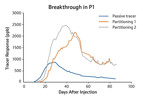
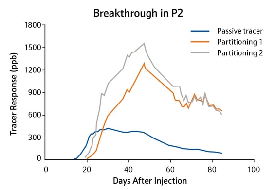
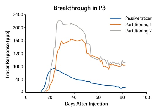
Figure 2 - Tracer response curves for partitioning and studies at tracerco.com/downloads/case-studies
non-partitioning tracers.
Phase Three
Examination of tracer behaviour revealed that new or modified streamlines were being formed within the
reservoir, reflecting the viscous nature of the ASP fluid and its higher oil displacement efficiency. Analysis of
the different arrival behaviours of partitioning and non-partitioning water tracers showed the residual oil
saturation dropped from 36-37% down to less than 2% of the waterflood-contacted pore volume, a significant enough improvement in oil recovery to validate the effectiveness of the ASP flood.
The Conclusion
Tracerco’s partitioning and non-partitioning tracers were a valuable tool to understand the reservoir and how
different development strategies affected recovery. In this tracer study, the operator used tracers to gain a
qualitative understanding of:
• Well-to-well connectivity
• Delineated flow streamlines in the reservoir
• Faulting and its effect on communication
• The extent and speed of water breakthrough
Furthermore, the analytical breakdown of results allowed Tracerco to add in a quantitative understanding of:
• Swept pore volume
• Remaining oil saturation
• Heterogeneity across the pilot area
• The effectiveness of water and polymer floods
In doing so, a technical partnership with Tracerco provided the needed confidence for traditionally high-risk financial decisions and maximised oil recovery from the formation.
Chemical tracer technology provides critical fluid flow information, accurately measuring water, gas and oil flow. It can help you to continuously monitor your reservoir and optimise drilling, completion and oil development strategies to maximise oil production in thousands of wells globally. To find out more, watch our webinar: Chemical tracer technology or download the case study.